Week 1 Lab: Breadboards, Multimeters and Switches
Physical computing looked like complete wizardry to me. Although I had toyed around a little bit with Arduino, I only liked the software part. When it came to hardware, things looked scary because I forgot all of the basic electronic principles or didn't know how to use certain basic tools such as the multimeter.
In the first week of ITP's physical computing class, I could learn and experiment some of the basics of electricity ... and here's what I've learned.
Before starting
Here are some concepts that I found important.
Voltage regulator
Voltage regulators let you convert voltage levels. For example, a 5-volt voltage regulator converts a higher DC input voltage into a 5-volt output voltage. In this picture, pin 1 is input, pin 2 is ground and pin 3 is output. Although I didn't use a voltage regulator because I used an Arduino Nano 33 which has built-in regulators, it will come handy when using a DC input.
Anodes and cathodes
Anode is where electricity moves into, cathode is where electricity goes out from. For example, an anode of the LED is the longer leg, which is connected to the voltage. The cathode of the LED is the shorter leg, which is connected to ground.
In a battery, you send electricity so the cathode is positive(+) while the anode is negative(-). However, in a LED you use electricity. So the anode is positive(+) while the cathode is negative(-). That was confusing...
Breadboards
A solderless breadboard has several rows of pins. The pins in the outer column (red/blue line) are connected vertically, while the pins in the inner columns are connected horizontally.
Fritzing
Fritzing lets you simulate circuits without having to work on the physical parts. If you are extra scared about short circuits and don't want my parts to explode like me, using Fritzing looks like a good idea.
Calculating resistors
Calculating resistor ohms, especially under dim light can be tiresome. This website helps calculating resistor ohms, but I haven't still figured out how to distinguish red and brown more easily. The only answer is to use a multimeter, I guess.
Lab
Connecting power supply
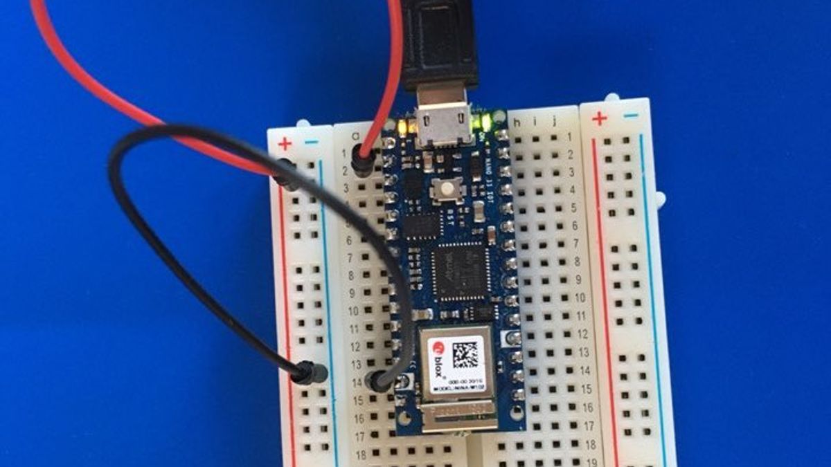
Since I don't have a DC power supply, I decided to use an Arduino Nano 33 IoT with Headers. I simply had to connect 2 jumper wires and a USB power supply to my laptop.

See the lights on? It works!
Using the multimeter
A multimeter is a tool for measuring voltages, resistance and currents. It can also measure continuity, which means there is electricity flowing between two points. You can test a multimeter by crossing two probes together.


Lighting
Using Arduino as a power source, I experimented with LEDs.


Switches
I added a pushbutton switch. Unfortunately I had bought a load of pushbutton switch(the ones you have to keep pressing) instead of normal ON/OFF switches. However the basic functionality is the same.


Key Takeaways
- Taking photos with multimeters were hard because I had to take pictures with one hand and try to put multimeter probes on circuits with another hand. It seems I need a proper camera stand for easy documentation.
- Organizing and storing parts was a fuss for me. I need to buy some labels especially for the voltage regulators having similar looks.
- Multimeters are useful for debugging things if they don't work.